Deploying the best E-Resources for Software Engineering Students

We at IT Engg Portal, provide all the Computer and IT Engineering students of Pune University with well compiled, easy to learn notes and other E-resources based on the curriculum

Power Point Presentations and Video Lectures for Download

We provide the most recommended power point presentations and Video Lectures from the most prominent Universities for most of the difficult subjects to ease your learning process

Bundling Codes for your Lab Practicals

Deploying the best of available E-Resources for Tech Preparation (Campus Placements)

The Complete Placement Guide

Our Team has worked hard to compile this E-Book for all students heading for Campus Placements. The book is a complete solution for Technical Preparation for Campus Placements.

Pune University's most viewed website for Computer and IT Engineering

With more than 4,00,0000 pageviews from 114 countries over the globe, we are now the most viewed website for Ebooks and other E- Resources in Computer and IT Engineering

Showing posts with label SE Pune University. Show all posts

Tuesday, August 14, 2012

SE 2008 Pattern Results are finally revealed : Pune University


     Pune University has finally rolled out the results for SE 2008 pattern after a long wait. This time unusually SE results were declared after the FE, TE and BE results were declared.  There were a lot of rumors spreading out about the results. The results which was supposed to be rolled out on 5th of August was again postponed for the 2nd time due to undisclosed reasons. But finally after a long wait, results  have finally  been given a Green signal.


Sunday, July 29, 2012

What is the difference between Von Neumann Architecture and Harvard Architecture ?

The Von Neumann and the Harvard Architecture is one important concept introduced in the basics of Computer Organization a subject which is included in the Engineering curriculum in 3rd semester for Information Technology Engineering and 4th semester for Computer Engineering in  Pune University.


 Today let us have a deeper look into both the architectures and then discuss the difference between the two.


The Von Neumann Architecture


In the von Neumann Architecture, the computer consisted of a CPU, memory and I/O devices. The program is stored in the memory. The CPU fetches an instruction from the memory at a time and executes it.
Thus, the instructions are executed sequentially which is a slow process. Neumann m/c are called control flow computer because instruction are executed sequentially as controlled by a program counter. To increase the speed, parallel processing of computer have been developed in which serial CPU’s are connected in parallel to solve a problem. Even in parallel computers, the basic building blocks are Neumann processors.
The von Neumann architecture is a design model for a stored-program digital computer that uses a processing unit and a single separate storage structure to hold both instructions and data. It is named after mathematician and early computer scientist John von Neumann. Such a computer implements a universal Turing machine, and the common "referential model" of specifying sequential architectures, in contrast with parallel architectures.
One shared memory for instructions (program) and data with one data bus and one address bus between processor and memory. Instructions and data have to be fetched in sequential order (known as the Von Neuman Bottleneck), limiting the operation bandwidth. Its design is simpler than that of the Harvard architecture. It is mostly used to interface to external memory.

Harvard Architecture

The term originated from the Harvard Mark 1 relay-based computer, which stored instructions on punched tape and data in relay latches.


Harvard Architecture: The Harvard architecture uses physically separate memories for their instructions and data, requiring dedicated buses for each of them. Instructions and operands can therefore be fetched simultaneously.
Different program and data bus widths are possible, allowing program and data memory to be better optimized to the architectural requirements. E.g.: If the instruction format requires 14 bits then program bus and memory can be made 14-bit wide, while the data bus and data memory remain 8-bit wide.

Harvard architecture is a computer architecture with physically separate storage and signal pathways for instructions and data. The term originated from the Harvard Mark I relay-based computer, which stored instructions on punched tape (24 bits wide) and data in electro-mechanical counters (23 digits wide). These early machines had limited data storage, entirely contained within the data processing unit, and provided no access to the instruction storage as data, making loading and modifying programs an entirely offline process.


Memory details

In a Harvard architecture, there is no need to make the two memories share characteristics. In particular, the word width, timing, implementation technology, and  memory address structure can differ. Instruction memory is often wider than data memory. In some systems, instructions can be stored in read-only memory while data  memory generally requires read-write memory. In some systems, there is much more instruction memory than data memory so instruction addresses are much wider than data addresses.

Contrast with other computer architectures


In a computer with the contrasting von Neumann architecture (and no cache), the CPU  can be either reading an instruction or reading/writing data from/to the memory. Both  cannot occur at the same time since the instructions and data use the same bus system. In a  computer using the Harvard architecture, the CPU can both read an instruction  and erform a data memory access at the same time, even without a cache. A Harvard architecture computer can thus be faster for a given circuit complexity because instruction fetches and data access do not contend for a single memory pathway.


The Modified Harvard architecture is very much like the Harvard architecture but provides a pathway between the instruction memory and the CPU that allows words  from the instruction memory to be treated as read-only data. This allows constant data, particularly text strings, to be accessed without first having to be copied into data memory, thus preserving more data memory for read/write variables. Special machine language instructions are provided to read data from the instruction memory. Most modern computers that are documented as Harvard Architecture are, in fact, Modified
Harvard Architecture.


Speed
In recent years the speed of the CPU has grown many times in comparison to the access speed of the main memory. Care needs to be taken to reduce the number of times main memory is accessed in order to maintain performance. If, for instance, every instruction run in the CPU requires an access to memory, the computer gains nothing for increased CPU speed — a problem referred to as being memory bound.


It is possible to make extremely fast memory but this is only practical for small amounts of memory for both cost and signal routing reasons. The solution is to provide a small amount of very fast memory known as a CPU cache which holds recently accessed data. As long as the memory that the CPU needs is in the cache, the performance hit is much smaller than it is when the cache has to turn around and get the data from the main memory. Cache tuning is an important aspect of computer  design.

Modern high performance CPU chip designs incorporate aspects of both Harvard and  von Neumann architecture. On-chip cache memory is divided into an instruction cache and a data cache. Harvard architecture is used as the CPU accesses the cache. In the case of a cache miss, however, the data is retrieved from the main memory, which is  not divided into separate instruction and data sections. Thus, while a von Neumann architecture is presented to the programmer, the hardware implementation gains the efficiencies of the Harvard architecture.


Uses
Harvard architectures are also frequently used in:
  • Specialized digital signal processors, DSPs, commonly used in audio or video processing products. For example, Blackfin processors by Analog Devices, Inc. use a Harvard architecture.
  •  Most general purpose small microcontrollers used in many electronics applications, such as the PIC by Microchip Technology, Inc., and AVR by Atmel Corp. These processors are characterized by having small amounts of program and data memory, and take advantage of the Harvard architecture and reduced instruction sets (RISC) to ensure that most instructions can be executed within only one machine cycle, which is not necessarily one clock cycle. The separate storage means the program and data memories can have different bit depths.

Example:
PICs have an 8-bit data word but (depending on specific range of PICs) a 12-, 14-, or 16-bit program word. This allows a single instruction to contain a full-size data constant. Other RISC architectures, for example the ARM, typically must use at least two instructions to load a full-size constant.
--------------------------------------------------

What is the difference between a von Neumann architecture and a Harvard architecture?


Harvard architecture has separate data and instruction busses, allowing transfers to be performed simultaneously on both busses. A von Neumann architecture has only one bus which is used for both data transfers and instruction fetches, and therefore data transfers and instruction fetches must be scheduled - they can not be performed at the same time.
It is possible to have two separate memory systems for a Harvard architecture. As long as data and instructions can be fed in at the same time, then it doesn't matter whether it comes from a cache or memory. But there are problems with this. Compilers generally embed data (literal pools) within the code, and it is often also necessary to be able to write to the instruction memory space, for example in the case of self modifying code, or, if an ARM debugger is used, to set software breakpoints in memory. If there are two completely separate, isolated memory systems, this is not possible. There must be some kind of bridge between the memory systems to allow this.
Using a simple, unified memory system together with a Harvard architecture is highly inefficient. Unless it is possible to feed data into both busses at the same time, it might be better to use a von Neumann architecture processor.
Use of caches
At higher clock speeds, caches are useful as the memory speed is proportionally slower. Harvard architectures tend to be targeted at higher performance systems, and so caches are nearly always used in such systems.
Von Neumann architectures usually have a single unified cache, which stores both instructions and data. The proportion of each in the cache is variable, which may be a good thing. It would in principle be possible to have separate instruction and data caches, storing data and instructions separately. This probably would not be very useful as it would only be possible to ever access one cache at a time.
Caches for Harvard architectures are very useful. Such a system would have separate caches for each bus. Trying to use a shared cache on a Harvard architecture would be very inefficient since then only one bus can be fed at a time. Having two caches means it is possible to feed both buses simultaneously....exactly what is necessary for a Harvard architecture.
This also allows to have a very simple unified memory system, using the same address space for both instructions and data. This gets around the problem of literal pools and self modifying code. What it does mean, however, is that when starting with empty caches, it is necessary to fetch instructions and data from the single memory system, at the same time. Obviously, two memory accesses are needed therefore before the core has all the data needed. This performance will be no better than a von Neumann architecture. However, as the caches fill up, it is much more likely that the instruction or data value has already been cached, and so only one of the two has to be fetched from memory. The other can be supplied directly from the cache with no additional delay. The best performance is achieved when both instructions and data are supplied by the caches, with no need to access external memory at all.
This is the most sensible compromise and the architecture used by ARMs Harvard processor cores. Two separate memory systems can perform better, but would be difficult to implement.

-------------------------------------------------------------------


Monday, April 16, 2012

What is Binary [Detailed Explanation]


We have all heard about the term 'binary' in our curriculum and many other technical theories. Often , you might have come across 32 bit , 64 bit and similar terms. We usually assume a lot of concepts which we might have overheard.  But till date some points still dont connect the picture you have in your mind. Today lets have a simple outlook towards the concept of Binary. 


What is binary?( The difference between Base 10 and Base 2)

Most of us have grown up in a base 10 world of numbers, by which I mean we have 10 ‘base’ numbers (0-9) from which we derive all other numbers. Once we’ve exhausted those, we move up a unit level – 10’s, 100’s, 1000’s – this form of counting is hammered into our brains from birth. In actual fact, it was only from the Roman period that we started counting in base 10. Before that, base 12 was the easiest, and people used their knuckles to count.
When we learn base 10 in elementary school, we often write out the units like this:
what is binary code
So the number 1990 actually consists of 1 x 1000, 9 x 100, 9 x 10, and 0 x 1. I’m sure I don’t need to explain base 10 any further than that.
But what if instead of having a full selection of 0,1,2,3,4,5,6,7,8,9 to work with as the base numbers – what if we only had 0, and 1. This is called base 2; and it’s also commonly referred to as binary. In a binary world, you can only count 0,1 – then you need to move to the next unit level.

Counting in Binary

It helps immensely if we write out the units when learning binary. In this case, instead of each additional unit being multiplied by 10, it’s multiplied by 2, giving us 1,2,4,8,16,32,64 … So to help calculate, we can write them out like this:
what is binary
In other words, the right-most value in a binary number represents how many 1’s. The next digit, to the left of that, represent how many 2’s. The next represents how many 4’s… and so.
With that knowledge, we can write out a table of counting in binary, with the equivalent base 10 value indicated on the left.
what is binary code
Spend a moment going over that until you can see exactly why 25 is written as 11001. You should be able to break it down as being 16+8+1 = 25.

Working backwards – base 10 to binary

You should now be able to figure out what value a binary number has by drawing a similar table and multiplying each unit. To switch a regular base 10 number to binary takes a little more effort. The first step is to find the largest binary unit that “fits into” the number. So for example, if we were doing 35, then the largest number from that table that fits into 35 is 32, so we would have a 1 there in that column. We then have a remainder of 3 – which would need a 2, and then finally a 1. So we get 100011.

8-bits, Bytes, and Octets

The table I’ve shown above is 8-bit, because we have a maximum of 8 zeroes and ones to use for our binary number. Thus, the maximum number we can possibly represent is 11111111,  or 255. This is why in order to represent any number from 0-255, we need at least 8-bits. Octet and Byte is simply another way of saying 8-bits. Therefore 1 Byte = 8 bits.

32 vs 64-bit Computing

Nowadays you often hear the terms 32-bit and 64-bit versions of Windows, and you may know that 32-bit Windows can only support up to 4 gigabytes of RAM. Why is that though?
It all comes down to memory addressing. Each bit of memory needs a unique address in order to access it. If we had an 8-bit memory addressing system, we would only be able to have a maximum of 256 bytes of memory. With a 32-bit memory addressing system (imagine extending the table above to have 32 binary unit columns), we can go anywhere up to4,294,967,296 ? 4 billion bytes, or in other words – 4 GIGAbytes. 64-bit computing essentially removes this limit by giving us up to 18 quintillion different addresses – a number most of us simply can’t fathom.

IPv4 Addressing

The latest worry in the computing world is all about IP addresses, in particular IPv4addresses, like these:
  • 192.168.0.1
  • 200.187.54.22
They actually consist of 4 numbers, each representing a value up to 255. Can you guess why? Yep, the whole address is represented by 4 octets (32 bits in total). This seemed like an awful lot of possible addresses (around 4 billion in fact) at the time the internet was first invented, but we’re rapidly running out now that everything in our life needs to be connected. To solve this, the new IPv6 uses 128 bits in total, giving us approximately 340 undecillion(put 38 zeroes on the end) addresses to play with.

Wednesday, November 16, 2011

Pune University : SE [Comp & IT] Dec 2010 Question Papers


Information Technology : 
SE  - 2010 Dec


Subject
Sem
Download
Discrete Structures
3
Computer Organization
3
Digital Electronics & Logic Design
3
Fundamentals of Data Structures
3
Humanities and Social Science
3


Computer Engineering  :
 SE - 2010 Dec


Subject
Sem
Download
Discrete Structures
3
P.P.S
3
Digital Electronics & Logic Design
3
Data Structures & Algorithm 
3
Humanities and Social Science
3


Friday, October 7, 2011

Stack Operations - Explanation with Animation


Stack Operations


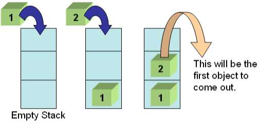
   The two operations that form the majority of the functionality of the stack are the operation of adding to the stack, and the operation of removing items from the stack.
to View a Simple Animation on Stack & Stack Operation

   For historical reasons the operation of adding items to a stack is called push. For similar reasons the operation of removing an item from a stack is usually referred to as pop.
There are a couple more operations that we must consider before we attempt to implement a stack. The first of these is an operation called init. This initialises the stack, and ensures that state of the software is in a known condition before we try to use it. Just about every structure that we will ever use will require an initialisation routine - get into the habit of writing the outline of the init operation first!

    As this is a course in developing software, we must also consider the possibility of errors. The easiest error to envisage for a stack is when a program tries to remove an item from an empty stack. This condition is called underflow, and if undetected will probably cause a series of mysterious errors before the program crashes. The method that we use to detect this problem is to use an operation called isEmpty to tell us if the stack is empty. If we try and take data from an empty stack the error condition is usually called underflow. Similarly there is a possibility that we might run out of space. To counter this we can provide an operation called isFull.

  Using this analysis we can conclude that we need to provide five operations to implement a stack. These operations are:
  1. init
  2. isEmpty
  3. isFull
  4. push
  5. pop
  If we can satisfactorily implement these operations we have implemented a stack. Note that we do not have to say at this stage exactly how these operations are implemented, or exactly how the data is held. There is more than one way of implementing a stack. In this Unit we are going to consider how to implement a stack using an array.

Array Implementation


The first decision that must be made is how big an array to declare to hold the data items in the stack. It is usually prudent to use a constant as the size of the stack. In C a declaration along the lines of:


#define STACKSIZE 10


will declare a stack size of 10 elements (from 0 to 9). If we need to change the size of the stack later we can just change this value and recompile. In addition to the data being held in the stack, we will need to hold data about the stack, in particular the number of entries being held in the stack. We need to hold the data about the stack in the same place as the data in the stack, so this probably means that we need to use a C struct. Trying to use meaningful variable names we have a declaration of:


struct stack{
   int top;
   int items[STACKSIZE];
};

now that we have the declaration of the structure we can make our function prototypes:

void init(struct stack *);
int isEmpty(struct stack);
int isFull(struct stack);
void push(struct stack *, int item);
int pop(struct stack *);

 
Only now do we have to start thinking about exactly how to implement the operations! The method used in this course is to add items at the location indicated by the index top, and then increment top. The first operation then is to write the init function. All this has to do is to set top to zero (the number of items in a newly created stack):

void init(struct stack * a_stack)
{
   a_stack->top=0;
}
Note the use of the "*" and "->" notation to allow us to change the values in the stack rather than copies of the values.

IsEmpty and IsFull
The next function to define is the isEmpty function.
int isEmpty(struct stack a_stack)
{
  if ( a_stack.top <= 0 )
    return TRUE;
  else
    return FALSE;
}
This function returns either true or false, depending on the value of top. If top is less than zero this means that an uncaught underflow has occurred. In theory this should not happen, but it costs us nothing extra to defend against this problem. We could just use the test for equality ( == ) at this point, but badly behaved code could cause a problem if the value of top skips past zero. Similarly, the isFull code looks like this:
int isFull(struct stack a_stack)
{
  if (a_stack.top < STACKSIZE )
    return FALSE;
  else
    return TRUE;
}
The only point to note in this code is the use of the constant STACKSIZE defined earlier. This is the bulk of the supporting code that we need to provide for our implementation of a stack.

Push and Pop

Stack adter init

It would now be appropriate to have a closer look at the push and pop operations.
This depicts the stack after the init operation has been executed. If we are programming in C then the contents of each of the elements of the stack will be filled with arbitrary bit patterns left over from the last time that the memory was used. Other programming languages may be kinder.

Push

The first thing that needs to be performed is a push operation. The diagram shows the changes to be made if the value 10 is pushed onto the stack:
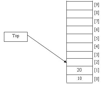
After the push operation, the array holds the pushed value in the location that used to be indexed by top, and top has now moved on to point to the next slot in the array, ready for the next push. The next step is to perform a second push. The second value to be pushed in this example is 20:
Before


After


Pop
Starting from the previous position, we will now show the process of popping an item from the stack. The stack pointer top is currently pointing to location 2. Aspop is the reverse operation from push, the activities should be carried out in reverse order. This means that top will be decremented, then the item being selected for the pop operation will be returned to the calling program. After the pop operation the stack will look as shown:
Before


After

Notice that the value 20 remains in the array, as we have not actually changed the value. The next time we call the push function the new value will be placed in the location, overwriting the current contents