Showing posts with label Mobile Computing. Show all posts
Monday, November 5, 2012
Cell Splitting - Mobile Computing : [BE - IT/Comp]
Article contributed by :
manoj@itportal.in
----------------------------------------------------------
We
have already studies in detail the concept of a cell, cluster, MS and the BS.
So, we will not discuss those all over again. Let us move straight into the
topic.
The concept of Cell
Splitting is quite self explanatory by its name itself. Cell splitting means to split up cells into smaller cells. The process of cell splitting is used to expand the capacity
(number of channels) of a mobile communication system. As a network grows, a
quite large number of mobile users in an area come into picture. Consider the
following scenario.
There are 100 people in a specific area. All of them
owns a mobile phone (MS) and are quite comfortable to communicate with each
other. So, a provision for all of them to mutually communicate must be made. As
there are only 100 users, a single base station (BS) is built in the middle of
the area and all these users’ MS are connected to it. All these 100 users now
come under the coverage area of a single base station. This coverage area is
called a cell. This is shown in Fig 2-1.
Fig 2-1. A single BS for 100 MS users.
But now, as time passed by, the number of
mobile users in the same area increased from 100 to 700. Now if the same BS has
to connect to these 700 users’ MS, obviously the BS will be overloaded. A
single BS, which served for 100 users is forced to serve for 700 users, which
is impractical. To reduce the load of this BS, we can use cell splitting. That
is, we will divide the above single cell into 7 separate adjacent cells, each
having its own BS. This is shown in Fig
2-2.
Fig 2-2. Single cell
split up into 7 cells
Now,
let us look into the big picture. Until now, we have discussed about cell
splitting in a small area. Now, we use this same concept to deal with large
networks. In a large network, it is not necessary to split up all the cells in
all the clusters. Certain BSes can handle the traffic well if their cells
(coverage areas) are split up. Only those cells must be ideal for cell
splitting. Fig 2-3 shows network
architecture with a few number of cells split up into smaller cells, without
affecting the other cells in the network.
Fig 2-3. Cell Splitting.
The concept of cell
splitting can further be applied to the split cells as well. That is, the split
up cells can further be split into a number of smaller cells to improve the
efficiency of the BS even more. Fig 2-4 shows a hierarchy of cell splitting.
Here, the master cells which have been split up
into smaller cells are known as macro cells. The split up cells are known as
micro cells. The innermost cells, split up by splitting the micro cells are
known as pico cells.
manoj@itportal.in
----------------------------------------------------------
Frequency Reuse - Mobile Computing : [BE : IT/Comp]
Article contributed by :
manoj@itportal.in
----------------------------------------------------------
Most
of you might be familiar with the concept of frequency reuse. We often come across this term in
Mobile Computing. Quite a straightforward and simple concept, but still it
requires a detailed explanation. This is one of the most common terms used in
the world of Cellular Telephony (Wireless Communication). Most cellular systems
use frequency reuse scheme to improve capacity and coverage. Let us understand
what exactly a cell mean and how they are related to frequencies.
In
a cellular system, each mobile station
(MS) is connected with its base
station (BS) via a radio link. The BS is responsible for sending the calls
to and from the MS, which lie in the coverage area of that BS. The coverage
area of a base station or a sector of a base station is known as a cell. Each
BS consists of a number of frequency channels, which serve as a link between
the MS and the BS. Every time, a call propagates through a channel which is
currently idle and receiving the best signal. As the coverage area of a BS can
be termed as a cell, we can also say
that a cell uses the frequency channels for call forwarding. These cells are
usually of hexagonal shape (this explanation is certainly not in the scope of
our discussion here). The Fig 1-1
shows a typical structure of a cell.
Fig
1-1. A cell.
A PCS (Personal
Communication System) is a combination of many such cells. So, a cell may be
surrounded by a large number of adjacent cells. This is shown in Fig 1-2.
Fig 1-2. Cells adjacent to each other
(Cluster).
Now,
let us look at a more general term used for the above structure- a cluster. A number of cells are
grouped to form a cluster. So, a cluster
is a collection of various cells. Now, after understanding the concepts of
cells and cluster, let us move into the actual concept of frequency reuse.
As
we have seen, cells use frequencies. But imagine two or more cells in a single
cluster using the same frequency. Obviously, there is a wide scope of
interference. So, it is always a better option to avoid two cells in a cluster
using the same frequencies. That is, inside a cluster, all the cells must use
different frequencies. A 3-cell cluster with all the adjacent cells using
different frequencies (F1, F2 and F3) is shown in Fig 1-3.
Fig 1-3. Cells in a
cluster using different frequencies.
But
this will definitely lead to a new problem. As the network grows, if every cell
in a system uses different frequencies, the frequency spectrum will be heavily
utilized. A large amount of frequencies will be utilized by these cells. A
solution to this problem is the Frequency Reuse.
All
the cells in a cluster must still have different frequencies, but these
frequencies can be reused by the cells in other clusters. This is the concept
of frequency reuse. That is, if
frequencies A, B, C, D, E, F and G are used by the cells in a 7-cell cluster,
these same frequencies A, B, C, D, E, F and G can be used by the cells in other
clusters. See Fig 1-4.
Fig
1-4. Frequency Reuse.
In the above figure, three different clusters
are shown with three different colors. Each of the 7 cells in each clusters use
different frequencies (A through G). But, the same frequencies (A through G)
are reused by the seven cells of each of the other clusters. Thus, the problems
of interfering frequencies as well as over-utilization of frequencies are
overcome using the concept of frequency reuse.
Article contributed by :
manoj@itportal.in
----------------------------------------------------------
Monday, October 31, 2011
GPRS - Mobile Computing [BE : Comp & IT]
11:59 AM
BE Pune University, gprs.GPRS, GSM, mc, Mobile Computing
GENERAL PACKET RADIO SERVICE (GPRS)
The standard bandwidth of 9.6kbps available for the data services is not sufficient for the requirements of today’s computers .To enhance the data transmission capabilities of GSM , two basic approaches were developed…….
1.High speed circuit switched data(HSCSD):---------
The first one is high speed circuit switched data . It allocates several TDMA slots within a TDMA frame .This allocation can be asymmetrical ,i.e., more slots can be allocated on the downlink than on the uplink ,which fits the typical user behavior of downloading more data .One problem of this configuration is that the MS is required to send and receive at the same time .It also has some disadvantages as it uses the connection oriented mechanisms of GSM . These are not at all efficient for computer data traffic, which is typically bursty and asymmetrical.
For n channels , HSCSD requires n times signaling during handover, connection set up and release . Each channel is treated separately. The probability of blocking or services degradation increase during handover , as in this case a BSC has to check resources for n channels , not just one .
2. GENERAL PACKET RADIO SERVICE (GPRS) :----------
The next step towards more flexible and powerful data transmission is GPRS .It is more efficient and cheapest because in this mode charging is based on volume not on connection time like HSCSD . The main advantage of GPRS is the ‘always on’ characteristic no connection has to be setup prior to data transfer. In GPRS time slots are not allocated in a fixed , pre determined manner but on demand .All time slots can be shared by the active users ;up-down link are allocated separately. Allocation of the slots is based on current load and operator preferences . The GPRS concept is independent of channel characteristic and of the type of channel ,and does not limit the maximum data rate.
GPRS offers a point-to-point (PTP) packet transfer service. One of the PTP version offered is the PTP connection oriented network services (PTP-CONS), which includes the ability of GPRS to maintain a virtual circuit upon change of the cell within the GSM network. The other PTP version offered is the PTP connectionless network service (PTP-CLNS) , which support applications that based on the internet protocol IP. Multicasting , called point-to-multipoint(PTM) service. Users of GPRS can specify a QoS-profile. This determine the service precedence ,reliability class and delay class of the transmission , and user data throughput. GPRS exhibit a large jitter compared to fixed networks.
The GPRS architecture introduces two new network elements , which are called GPRS support nodes(GSN) and work like router .The gateway GPRS node (GGSN) is the interworking unit between the GPRS network and packet data networks(PDN). This node contains routing information for GPRS users ,performs address conversions , and tunnels data to a user via encapsulation . The GGSN is connected to external networks to external networks via Gi interface and transfer packets to the SGSN via an IP-based GPRS backbone network. The other new element is the serving GPRS supports node(SGSN) which supports the MS via the Gb interface. Packet data is transmitted from a PDN , via the GGSN and SGSN directly to the BSS and finally to the MS . The MSC which is responsible for data transport in the traditional circuit-switched GSM, is used for signaling in the GPRS scenario. Before sending any data over the GPRS network ,an MS must attach to it ,following the procedure of the mobility management .The attachment procedure includes assign a temporal identifier ,called a temporary logical link identity (TLLI) ,and a ciphering key sequence number(CKSN) for data encryption.

GPRS ARCHITECTURE REFERENCE MODEL
The protocol architecture of the transmission for GPRS is given in the figure . All the data within the GPRS backbone ,i.e. ,between the GSNs , is transferred using the GPRS tunneling protocol(GTP) . GTP can use two different transport layer protocols , TCP or UDP. The network protocol for the GPRS backbone is IP. To adapt the different characteristics of the underlying networks , the subnetwork dependent convergence protocol(SNDCP) is used between an SGSN and the MS. A base station subsystem GPRS protocol(BSSGP) is used to convey routing and QoS-related information between the BSS and SGSN.BSSGP does not perform error connection and works on the top of a frame relay network .Finally , radio link dependent protocol are needed to transfer data over the Um interface .

GPRS TRANSMISSION PLANE PROTOCOL REFEERNCE MODEL
The radio link protocol (RLC) provides a reliable link , while the MAC control access with signaling procedure for the radio channel and mapping of LLC frames onto the GSM physical channels . Capacity can be allocated on demand and shared between circuit-switched channels and GPRS. This allocation can be done dynamically with load supervision or alternatively, capacity can be pre-allocated. The application uses TCP on top of IP , IP packets are tunneled to the GGSN, witch forwards them into PDN . All PDNs forward their packets for a GPRS user to the GGSN ,the GGSN asks the current SGSN for tunnel parameters ,and forward their packets via SGSN to the MS. All MS are assigned private IP address which are then translated into global address at GGSN using NAT. The advantage of this approach is the inherent protection of MSs from attacks. Private address are not routed through the internet so it not possible to reach an MS from the internet. This is also a disadvantage if MS wants to offer a service using a fixed , globally visible IP address.
1.High speed circuit switched data(HSCSD):---------
The first one is high speed circuit switched data . It allocates several TDMA slots within a TDMA frame .This allocation can be asymmetrical ,i.e., more slots can be allocated on the downlink than on the uplink ,which fits the typical user behavior of downloading more data .One problem of this configuration is that the MS is required to send and receive at the same time .It also has some disadvantages as it uses the connection oriented mechanisms of GSM . These are not at all efficient for computer data traffic, which is typically bursty and asymmetrical.
For n channels , HSCSD requires n times signaling during handover, connection set up and release . Each channel is treated separately. The probability of blocking or services degradation increase during handover , as in this case a BSC has to check resources for n channels , not just one .
2. GENERAL PACKET RADIO SERVICE (GPRS) :----------
The next step towards more flexible and powerful data transmission is GPRS .It is more efficient and cheapest because in this mode charging is based on volume not on connection time like HSCSD . The main advantage of GPRS is the ‘always on’ characteristic no connection has to be setup prior to data transfer. In GPRS time slots are not allocated in a fixed , pre determined manner but on demand .All time slots can be shared by the active users ;up-down link are allocated separately. Allocation of the slots is based on current load and operator preferences . The GPRS concept is independent of channel characteristic and of the type of channel ,and does not limit the maximum data rate.
GPRS offers a point-to-point (PTP) packet transfer service. One of the PTP version offered is the PTP connection oriented network services (PTP-CONS), which includes the ability of GPRS to maintain a virtual circuit upon change of the cell within the GSM network. The other PTP version offered is the PTP connectionless network service (PTP-CLNS) , which support applications that based on the internet protocol IP. Multicasting , called point-to-multipoint(PTM) service. Users of GPRS can specify a QoS-profile. This determine the service precedence ,reliability class and delay class of the transmission , and user data throughput. GPRS exhibit a large jitter compared to fixed networks.
The GPRS architecture introduces two new network elements , which are called GPRS support nodes(GSN) and work like router .The gateway GPRS node (GGSN) is the interworking unit between the GPRS network and packet data networks(PDN). This node contains routing information for GPRS users ,performs address conversions , and tunnels data to a user via encapsulation . The GGSN is connected to external networks to external networks via Gi interface and transfer packets to the SGSN via an IP-based GPRS backbone network. The other new element is the serving GPRS supports node(SGSN) which supports the MS via the Gb interface. Packet data is transmitted from a PDN , via the GGSN and SGSN directly to the BSS and finally to the MS . The MSC which is responsible for data transport in the traditional circuit-switched GSM, is used for signaling in the GPRS scenario. Before sending any data over the GPRS network ,an MS must attach to it ,following the procedure of the mobility management .The attachment procedure includes assign a temporal identifier ,called a temporary logical link identity (TLLI) ,and a ciphering key sequence number(CKSN) for data encryption.
GPRS ARCHITECTURE REFERENCE MODEL
The protocol architecture of the transmission for GPRS is given in the figure . All the data within the GPRS backbone ,i.e. ,between the GSNs , is transferred using the GPRS tunneling protocol(GTP) . GTP can use two different transport layer protocols , TCP or UDP. The network protocol for the GPRS backbone is IP. To adapt the different characteristics of the underlying networks , the subnetwork dependent convergence protocol(SNDCP) is used between an SGSN and the MS. A base station subsystem GPRS protocol(BSSGP) is used to convey routing and QoS-related information between the BSS and SGSN.BSSGP does not perform error connection and works on the top of a frame relay network .Finally , radio link dependent protocol are needed to transfer data over the Um interface .

GPRS TRANSMISSION PLANE PROTOCOL REFEERNCE MODEL
The radio link protocol (RLC) provides a reliable link , while the MAC control access with signaling procedure for the radio channel and mapping of LLC frames onto the GSM physical channels . Capacity can be allocated on demand and shared between circuit-switched channels and GPRS. This allocation can be done dynamically with load supervision or alternatively, capacity can be pre-allocated. The application uses TCP on top of IP , IP packets are tunneled to the GGSN, witch forwards them into PDN . All PDNs forward their packets for a GPRS user to the GGSN ,the GGSN asks the current SGSN for tunnel parameters ,and forward their packets via SGSN to the MS. All MS are assigned private IP address which are then translated into global address at GGSN using NAT. The advantage of this approach is the inherent protection of MSs from attacks. Private address are not routed through the internet so it not possible to reach an MS from the internet. This is also a disadvantage if MS wants to offer a service using a fixed , globally visible IP address.
11:55 AM
BE Pune University, gprs, gprs.GPRS, mc, mobile, Mobile Computing, sem 7
GENERAL PACKET RADIO SERVICE (GPRS)
The standard bandwidth of 9.6kbps available for the data services is not sufficient for the requirements of today’s computers .To enhance the data transmission capabilities of GSM , two basic approaches were developed…….
1.High speed circuit switched data(HSCSD):---------
The first one is high speed circuit switched data . It allocates several TDMA slots within a TDMA frame .This allocation can be asymmetrical ,i.e., more slots can be allocated on the downlink than on the uplink ,which fits the typical user behavior of downloading more data .One problem of this configuration is that the MS is required to send and receive at the same time .It also has some disadvantages as it uses the connection oriented mechanisms of GSM . These are not at all efficient for computer data traffic, which is typically bursty and asymmetrical.
For n channels , HSCSD requires n times signaling during handover, connection set up and release . Each channel is treated separately. The probability of blocking or services degradation increase during handover , as in this case a BSC has to check resources for n channels , not just one .
2. GENERAL PACKET RADIO SERVICE (GPRS) :----------
The next step towards more flexible and powerful data transmission is GPRS .It is more efficient and cheapest because in this mode charging is based on volume not on connection time like HSCSD . The main advantage of GPRS is the ‘always on’ characteristic no connection has to be setup prior to data transfer. In GPRS time slots are not allocated in a fixed , pre determined manner but on demand .All time slots can be shared by the active users ;up-down link are allocated separately. Allocation of the slots is based on current load and operator preferences . The GPRS concept is independent of channel characteristic and of the type of channel ,and does not limit the maximum data rate.
GPRS offers a point-to-point (PTP) packet transfer service. One of the PTP version offered is the PTP connection oriented network services (PTP-CONS), which includes the ability of GPRS to maintain a virtual circuit upon change of the cell within the GSM network. The other PTP version offered is the PTP connectionless network service (PTP-CLNS) , which support applications that based on the internet protocol IP. Multicasting , called point-to-multipoint(PTM) service. Users of GPRS can specify a QoS-profile. This determine the service precedence ,reliability class and delay class of the transmission , and user data throughput. GPRS exhibit a large jitter compared to fixed networks.
The GPRS architecture introduces two new network elements , which are called GPRS support nodes(GSN) and work like router .The gateway GPRS node (GGSN) is the interworking unit between the GPRS network and packet data networks(PDN). This node contains routing information for GPRS users ,performs address conversions , and tunnels data to a user via encapsulation . The GGSN is connected to external networks to external networks via Gi interface and transfer packets to the SGSN via an IP-based GPRS backbone network. The other new element is the serving GPRS supports node(SGSN) which supports the MS via the Gb interface. Packet data is transmitted from a PDN , via the GGSN and SGSN directly to the BSS and finally to the MS . The MSC which is responsible for data transport in the traditional circuit-switched GSM, is used for signaling in the GPRS scenario. Before sending any data over the GPRS network ,an MS must attach to it ,following the procedure of the mobility management .The attachment procedure includes assign a temporal identifier ,called a temporary logical link identity (TLLI) ,and a ciphering key sequence number(CKSN) for data encryption.

GPRS ARCHITECTURE REFERENCE MODEL
The protocol architecture of the transmission for GPRS is given in the figure . All the data within the GPRS backbone ,i.e. ,between the GSNs , is transferred using the GPRS tunneling protocol(GTP) . GTP can use two different transport layer protocols , TCP or UDP. The network protocol for the GPRS backbone is IP. To adapt the different characteristics of the underlying networks , the subnetwork dependent convergence protocol(SNDCP) is used between an SGSN and the MS. A base station subsystem GPRS protocol(BSSGP) is used to convey routing and QoS-related information between the BSS and SGSN.BSSGP does not perform error connection and works on the top of a frame relay network .Finally , radio link dependent protocol are needed to transfer data over the Um interface .

GPRS TRANSMISSION PLANE PROTOCOL REFEERNCE MODEL
The radio link protocol (RLC) provides a reliable link , while the MAC control access with signaling procedure for the radio channel and mapping of LLC frames onto the GSM physical channels . Capacity can be allocated on demand and shared between circuit-switched channels and GPRS. This allocation can be done dynamically with load supervision or alternatively, capacity can be pre-allocated. The application uses TCP on top of IP , IP packets are tunneled to the GGSN, witch forwards them into PDN . All PDNs forward their packets for a GPRS user to the GGSN ,the GGSN asks the current SGSN for tunnel parameters ,and forward their packets via SGSN to the MS. All MS are assigned private IP address which are then translated into global address at GGSN using NAT. The advantage of this approach is the inherent protection of MSs from attacks. Private address are not routed through the internet so it not possible to reach an MS from the internet. This is also a disadvantage if MS wants to offer a service using a fixed , globally visible IP address.
1.High speed circuit switched data(HSCSD):---------
The first one is high speed circuit switched data . It allocates several TDMA slots within a TDMA frame .This allocation can be asymmetrical ,i.e., more slots can be allocated on the downlink than on the uplink ,which fits the typical user behavior of downloading more data .One problem of this configuration is that the MS is required to send and receive at the same time .It also has some disadvantages as it uses the connection oriented mechanisms of GSM . These are not at all efficient for computer data traffic, which is typically bursty and asymmetrical.
For n channels , HSCSD requires n times signaling during handover, connection set up and release . Each channel is treated separately. The probability of blocking or services degradation increase during handover , as in this case a BSC has to check resources for n channels , not just one .
2. GENERAL PACKET RADIO SERVICE (GPRS) :----------
The next step towards more flexible and powerful data transmission is GPRS .It is more efficient and cheapest because in this mode charging is based on volume not on connection time like HSCSD . The main advantage of GPRS is the ‘always on’ characteristic no connection has to be setup prior to data transfer. In GPRS time slots are not allocated in a fixed , pre determined manner but on demand .All time slots can be shared by the active users ;up-down link are allocated separately. Allocation of the slots is based on current load and operator preferences . The GPRS concept is independent of channel characteristic and of the type of channel ,and does not limit the maximum data rate.
GPRS offers a point-to-point (PTP) packet transfer service. One of the PTP version offered is the PTP connection oriented network services (PTP-CONS), which includes the ability of GPRS to maintain a virtual circuit upon change of the cell within the GSM network. The other PTP version offered is the PTP connectionless network service (PTP-CLNS) , which support applications that based on the internet protocol IP. Multicasting , called point-to-multipoint(PTM) service. Users of GPRS can specify a QoS-profile. This determine the service precedence ,reliability class and delay class of the transmission , and user data throughput. GPRS exhibit a large jitter compared to fixed networks.
The GPRS architecture introduces two new network elements , which are called GPRS support nodes(GSN) and work like router .The gateway GPRS node (GGSN) is the interworking unit between the GPRS network and packet data networks(PDN). This node contains routing information for GPRS users ,performs address conversions , and tunnels data to a user via encapsulation . The GGSN is connected to external networks to external networks via Gi interface and transfer packets to the SGSN via an IP-based GPRS backbone network. The other new element is the serving GPRS supports node(SGSN) which supports the MS via the Gb interface. Packet data is transmitted from a PDN , via the GGSN and SGSN directly to the BSS and finally to the MS . The MSC which is responsible for data transport in the traditional circuit-switched GSM, is used for signaling in the GPRS scenario. Before sending any data over the GPRS network ,an MS must attach to it ,following the procedure of the mobility management .The attachment procedure includes assign a temporal identifier ,called a temporary logical link identity (TLLI) ,and a ciphering key sequence number(CKSN) for data encryption.
GPRS ARCHITECTURE REFERENCE MODEL
The protocol architecture of the transmission for GPRS is given in the figure . All the data within the GPRS backbone ,i.e. ,between the GSNs , is transferred using the GPRS tunneling protocol(GTP) . GTP can use two different transport layer protocols , TCP or UDP. The network protocol for the GPRS backbone is IP. To adapt the different characteristics of the underlying networks , the subnetwork dependent convergence protocol(SNDCP) is used between an SGSN and the MS. A base station subsystem GPRS protocol(BSSGP) is used to convey routing and QoS-related information between the BSS and SGSN.BSSGP does not perform error connection and works on the top of a frame relay network .Finally , radio link dependent protocol are needed to transfer data over the Um interface .

GPRS TRANSMISSION PLANE PROTOCOL REFEERNCE MODEL
The radio link protocol (RLC) provides a reliable link , while the MAC control access with signaling procedure for the radio channel and mapping of LLC frames onto the GSM physical channels . Capacity can be allocated on demand and shared between circuit-switched channels and GPRS. This allocation can be done dynamically with load supervision or alternatively, capacity can be pre-allocated. The application uses TCP on top of IP , IP packets are tunneled to the GGSN, witch forwards them into PDN . All PDNs forward their packets for a GPRS user to the GGSN ,the GGSN asks the current SGSN for tunnel parameters ,and forward their packets via SGSN to the MS. All MS are assigned private IP address which are then translated into global address at GGSN using NAT. The advantage of this approach is the inherent protection of MSs from attacks. Private address are not routed through the internet so it not possible to reach an MS from the internet. This is also a disadvantage if MS wants to offer a service using a fixed , globally visible IP address.
Handover/Handoff Scenarios in GSM System - Mobile Computing
11:52 AM
BE Pune University, Comp, handoff, handoff mechanism, IT, maho, mc, mcho, Mobile Computing, ncho, sem 7
What is Handoff?
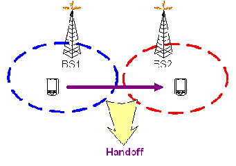
Handoff is the process of changing the channel associated with the current connection while a call is in progress. It is often initiated either by crossing a cell boundary or by a deterioration in quality of the signal in the current channel.
Poorly designed handoff schemes tend to generate very heavy signaling traffic
and, thereby, a dramatic decrease in quality of service (QoS)
HANDOFF DECISION
There are numerous methods for performing handoff, at least as many as the kinds of state information that have been defined for MSs, as well as the kinds of network entities that maintain the state information. The decision-making process of handoff may be centralized or decentralized (i.e., the handoff decision may be made at the MS or network) From the decision process point of view, one can find at least three different kinds of handoff decisions.
In a network-controlled handoff protocol, the network makes a handoff decision based on the measurements of the MSs at a number of BSs. In general, the handoff process takes 100–200 ms. Information about the signal quality for all users is available at a single point in the network that facilitates appropriate resource allocation. Network-controlled handoff is used in first-generation analog systems such as AMPS (advanced mobile phone system), TACS (total access communication system), and NMT (advanced mobile phone system).
Handover scenarios in GSM systems
Intracell handover
The easiest type of handover is intracell handover where either the physical channel or the associated timeslot configuration is changed. This may become necessary if the connection on a physical channel is impaired. To evaluate connection quality, the mobile phone continuously transmits the measured RXLev (receive level measured by the telephone) and RXQual (bit error ratio determined) values to the base station. If the base station wants to hand over the telephone to another physical channel, all it needs to do is to inform the telephone about the new channel number and the new timeslot configuration. The telephone changes directly to the new channel and is able to maintain both its previous settings for timing and the base station parameters.
Intercell handover
If the mobile phone moves from one cell to another during a call, it must be handed over to the new cell. If the neighbour cell is time-synchronous with the current cell, the base station is able to effect a finely synchronized intercell handover. In this case, the mobile phone is transmitted on the new physical channel in the neighbour cell. Moreover, the mobile phone must be informed about the vital parameters of the new cell.
The mobile phone then optionally transmits four access bursts on the new channel. Compared to the normal bursts, these are shortened which is why they cannot cause interference with other calls even if the timing is slightly incorrect. If necessary, timing is corrected in a next step and the call continued. If the two cells with time offset are synchronous, the base station will effect a pseudo-synchronized or presynchronized intercell handover. This handover is similar to the finely synchronized intercell handover, but differs in that the mobile phone is provided with information about the time offset. Usually, however, a non-synchronized intercell handover takes place. In this case, the mobile phone transmits up to 64 access bursts on the new channel by means of which the new base station determines the timing and hands it over to the mobile phone. The mobile phone then reestablishes the call connection with the correct timing.
The base station requires the mobile phone’s help in order to know the new cell to hand it over to. By means of the neighbour cell list, the base station informs the mobile phone about the RF channels for the BCCH that are used by the neighbour cells. The mobile phone now cyclically measures the RF level on these channels and transmits the measurement results to the base station. Based on this information, the base station determines the point in time at which the mobile phone is handed over to which cell. Changing the physical
channel both for the call and for the BCCH information is key to intercell handover.
Handoff is the process of changing the channel associated with the current connection while a call is in progress. It is often initiated either by crossing a cell boundary or by a deterioration in quality of the signal in the current channel.
Poorly designed handoff schemes tend to generate very heavy signaling traffic
and, thereby, a dramatic decrease in quality of service (QoS)
HANDOFF DECISION
There are numerous methods for performing handoff, at least as many as the kinds of state information that have been defined for MSs, as well as the kinds of network entities that maintain the state information. The decision-making process of handoff may be centralized or decentralized (i.e., the handoff decision may be made at the MS or network) From the decision process point of view, one can find at least three different kinds of handoff decisions.
- Network-Controlled Handoff
In a network-controlled handoff protocol, the network makes a handoff decision based on the measurements of the MSs at a number of BSs. In general, the handoff process takes 100–200 ms. Information about the signal quality for all users is available at a single point in the network that facilitates appropriate resource allocation. Network-controlled handoff is used in first-generation analog systems such as AMPS (advanced mobile phone system), TACS (total access communication system), and NMT (advanced mobile phone system).
- Mobile-Assisted Handoff
- Mobile-Controlled Handoff
Handover scenarios in GSM systems
Intracell handover
The easiest type of handover is intracell handover where either the physical channel or the associated timeslot configuration is changed. This may become necessary if the connection on a physical channel is impaired. To evaluate connection quality, the mobile phone continuously transmits the measured RXLev (receive level measured by the telephone) and RXQual (bit error ratio determined) values to the base station. If the base station wants to hand over the telephone to another physical channel, all it needs to do is to inform the telephone about the new channel number and the new timeslot configuration. The telephone changes directly to the new channel and is able to maintain both its previous settings for timing and the base station parameters.
Intercell handover
If the mobile phone moves from one cell to another during a call, it must be handed over to the new cell. If the neighbour cell is time-synchronous with the current cell, the base station is able to effect a finely synchronized intercell handover. In this case, the mobile phone is transmitted on the new physical channel in the neighbour cell. Moreover, the mobile phone must be informed about the vital parameters of the new cell.
The mobile phone then optionally transmits four access bursts on the new channel. Compared to the normal bursts, these are shortened which is why they cannot cause interference with other calls even if the timing is slightly incorrect. If necessary, timing is corrected in a next step and the call continued. If the two cells with time offset are synchronous, the base station will effect a pseudo-synchronized or presynchronized intercell handover. This handover is similar to the finely synchronized intercell handover, but differs in that the mobile phone is provided with information about the time offset. Usually, however, a non-synchronized intercell handover takes place. In this case, the mobile phone transmits up to 64 access bursts on the new channel by means of which the new base station determines the timing and hands it over to the mobile phone. The mobile phone then reestablishes the call connection with the correct timing.
The base station requires the mobile phone’s help in order to know the new cell to hand it over to. By means of the neighbour cell list, the base station informs the mobile phone about the RF channels for the BCCH that are used by the neighbour cells. The mobile phone now cyclically measures the RF level on these channels and transmits the measurement results to the base station. Based on this information, the base station determines the point in time at which the mobile phone is handed over to which cell. Changing the physical
channel both for the call and for the BCCH information is key to intercell handover.
Intersystem handover
If the mobile phone leaves a cell and no new cell can be found in the same system, the base station can hand over an appropriately equipped mobile phone to a cell in another system. These intersystem handovers are highly complex because two technically disparate systems must be combined with each other. Basically, there are two handover options from WCDMA to GSM: In the case of blind handover, the base station simply transmits the mobile phone with all relevant parameters to the new cell. The mobile phone changes “blindly” to the GSM cell, i.e. it has not yet received any information about the timing there. It will first contact the transmitted BCCH channel, where it tries to achieve the frequency and time synchronization within 800 ms. Next, it will switch to the handed-over physical voice channel, where it will carry out the same sequence as with the non-synchronized intercell handover.
For the second type of handover from WCDMA to GSM, the compressed mode is used within the WCDMA cell; in this mode, transmission and reception gaps occur during the transmission between base station and mobile phone. During these gaps, the mobile phone can measure and analyze the nearby GSM cells. For this purpose, the base station, similar to the GSM system, provides a neighbour cell list, and the mobile phone transfers the measurement results to the base station. The actual handover in the compressed mode is basically analogous to blind handover.
There is, of course, an intersystem handover from GSM to WCDMA. A special neighbour cell list for WCDMA cells was established in GSM to support this handover.
Saturday, October 8, 2011
Generations of Wireless Network : 1G, 2G, 3G & 4G - Mobile Computing
1G, which stands for "first generation," refers to the first generation of wireless telecommunication technology, more popularly known as cellphones. A set of wireless standards developed in the 1980's, 1G technology replaced 0G technology, which featured mobile radio telephones and such technologies as Mobile Telephone System (MTS), Advanced Mobile Telephone System (AMTS), Improved Mobile Telephone Service (IMTS), and Push to Talk (PTT).
Second Generation (2G)
Second generation (2g) telephone technology is based on GSM or in other words global system for mobile communication. Second generation was launched in Finland in the year 1991.
2.5G
The packet switched technology has grown in importance with the rise of the Internet and Internet protocol (IP). But as IP too has its own weaknesses, circuit-switched services are not going to disappear. Transmission control protocol (TCP) provides a virtual end-toend connection for reliability. Although Telnet is still used as a standard protocol for remote access to computer hosts, the main protocols in use today are HTTP for Web servers, SMTP for e-mail, andSNMP for network management. The GPRS (2.5G) core network and service characteristics. Although GPRS is an extension to the radio access network, it requires whole new packetbased IP data links, servers, and gateways in the core network. Thus GPRS adds several new components besides changing the existing GSM or TDMA network.
GPRS is important because it helps operators, vendors, content providers, and users prepare for 3G, as many concepts of GPRS live on in 3G, and we will need these enhancements to 2G networks for ten years or more. At the moment, wireless network technologies are somewhere between 2G and 2.5G. The second generation of mobile communications technology was all about digital PCS. The problem, however, was that much of the digital network was implemented for, or overlaid onto, proprietary networking equipment. Taken together, 2G and 2.5G technologies are far from seamless.
Some of the companies trying 4G mobile communication at 100 Mbps for mobile users and up to 1 Gbps over fixed stations. They planned on publicly launching their first commercial wireless network around 2010.
Unlike its successor, 2G, which made use of digital signals, 1G wireless networks used analog radio signals. Through 1G, a voice call gets modulated to a higher frequency of about 150MHz and up as it is transmitted between radio towers. This is done using a technique called Frequency-Division Multiple Access (FDMA).
- Advanced Mobile Phone System (AMPS) was a 1G standard used in the United States.
- Nordic Mobile Telephone (NMT) was a 1G standard used in Nordic countries (Denmark, Finland, Iceland, Norway and Sweden), as well as in its neighboring countries Switzerland and Netherlands, Eastern Europe, and Russia.
- Italy used a telecommunications system called RTMI.
- In the United Kingdom, Total Access Communication System (TACS) was used.
- France used Radiocom 2000.
Lets have a look at this animation..to have an overview of 1G -4G and then explore more oneach of them.
Second Generation (2G)
2g Architecture
Second generation (2g) telephone technology is based on GSM or in other words global system for mobile communication. Second generation was launched in Finland in the year 1991.
How 2G works, Uses of 2G technology
(Second Generation technology)
2G network allows for much greater penetration intensity. 2G technologies enabled the various mobile phone networks to provide the services such as text messages, picture messages and MMS (multi media messages). 2G technology is more efficient. 2G technology holds sufficient security for both the sender and the receiver. All text messages are digitally encrypted. This digital encryption allows for the transfer of data in such a way that only the intended receiver can receive and read it
Benefits of 2G technology (Second Generation) es the voice clarity and reduces noise in the line. Digital signals are considered environment friendly. The use of digital data service assists mobile network operators to introduce short message service over the cellular phones. Digital encryption has provided secrecy and safety to the data and voice calls. The use of 2G technology requires strong digital signals to help mobile phones work. If there is no network coverage in any specific area, digital signals would be weak.
2.5G
The mobile technology using general packet radio service (GPRS) standard has been termed as 2.5G. 2.5G systems enhance the data capacity of GSM and mitigate some of its limitations. GPRS adds packet-switched capa- bilities to existing GSM and TDMA networks. Working on the basis of emails, it sends tex and graphics-rich data as packets at very fast speed.The circuit-switched technology has a long and successful history but it is inefficient for short data transactionsand always-onservice.
GPRS is important because it helps operators, vendors, content providers, and users prepare for 3G, as many concepts of GPRS live on in 3G, and we will need these enhancements to 2G networks for ten years or more. At the moment, wireless network technologies are somewhere between 2G and 2.5G. The second generation of mobile communications technology was all about digital PCS. The problem, however, was that much of the digital network was implemented for, or overlaid onto, proprietary networking equipment. Taken together, 2G and 2.5G technologies are far from seamless.
3G Technology
If you want augmented bandwidth, multiple mobile applications and clarity of digital signals, then3G (Thrid Generation Technology) is your gateway. GSM technology was able to transfer circuit switched data over the network. The use of 3G technology is also able to transmit packet switch data efficiently at better and increased bandwidth. 3G mobile technologies proffers more advanced services to mobile users. It can help many multimedia services to function. The spectral efficiency of 3G technology is better than 2G technologies. Spectral efficiency is the measurement of rate of information transfer over any communication sytem. 3G is also known as IMT-2000.
|
3G technologies make use of TDMA and CDMA. 3G (Thrid Generation Technology) technologies make use of value added services like mobile television, GPS (global positioning system) and video conferencing. The basic feature of 3G Technology (Thrid Generation Technology) is fast data transfer rates. However this feature is not currently working properly because, ITU 200 is still making decision to fix the data rates. It is expected that 2mbit/sec for stationary users, while 348kbits when moving or traveling. ITU sell various frequency rates in order to make use of broadband technologies. Network authentication has won the trust of users, because the user can rely on its network as a reliable source of transferring data.3G technology is much flexible, because it is able to support the 5 major radio technologies. These radio technologies operate under CDMA, TDMA and FDMA.CDMA holds for IMT-DS (direct spread), IMT-MC (multi carrier). TDMA accounts for IMT-TC (time code), IMT-SC (single carrier). FDMA has only one radio interface known as IMT-FC or frequency code. Third generation technology is really affordable due to the agreement of industry. This agreement took pace in order to increase its adoption by the users. 3G (Thrid Generation Technology) system is compatible to work with the 2G technologies. 3G (Thrid Generation Technology)technologies holds the vision that they should be expandable on demand. The aim of the 3G (Thrid Generation Technology) is to allow for more coverage and growth with minimum investment.
There are many 3G technologies as W-CDMA, GSM EDGE, UMTS, DECT, WiMax and CDMA 2000.Enhanced data rates for GSM evolution or EDGE is termed to as a backward digital technology, because it can operate with older devices. EDGE allows for faster data transfer than existing GSM.EDGE was introduced by AT& T in 2003.EDGE has increased the GSM coverage up to three times more. EDGE is a 3G Technology (Thrid Generation Technology); therefore it can be used for packet switched systems. Universal mobile telecommunications systems .UMTS conforms to ITU IMT 2000 standard. It is complex network and allows for covering radio access, core network and USIM (subscriber identity module). It is a relatively expensive technology for the network operators because it requires new and separate infrastructure for its coverage. The GSM is the base of this technology. CDMA is also referred to as IMT-MC. this technology is close to 2G technology GSM because it is also backward compatible. Digital enhanced cordless telecommunications (DECT) is another 3G Technology (Thrid Generation Technology). DETC was developed by European telecommunications standards institute; however it is now widely popular in the other countries of the world as well.
What is 4G technology
When talking about 4G, question comes to our mind is what is 4G Technology. 4G is short forFourth (4th) Generation Technology. 4G Technology is basically the extension in the 3G technology with more bandwidth and services offers in the 3G. But at this time nobody exactly knows the true 4G definition. Some people say that 4G technology is the future technologies that are mostly in their maturity period. The expectation for the 4G technology is basically the high quality audio/video streaming over end to end Internet Protocol. If the Internet Protocol (IP) multimedia sub-system movement achieves what it going to do, nothing of this possibly will matter. WiMAX or mobile structural design will become progressively more translucent, and therefore the acceptance of several architectures by a particular network operator ever more common.
|
4G Technology offers high data rates that will generate new trends for the market and prospects for established as well as for new telecommunication businesses. 4G networks, when tied together with mobile phones with in-built higher resolution digital cameras and also High Definition capabilities will facilitate video blogs.
After successful implementation, 4G technology is likely to enable ubiquitous computing, that will simultaneously connects to numerous high date speed networks offers faultless handoffs all over the geographical regions. Many network operators possibly utilize technologies for example; wireless mesh networks and cognitive radio network to guarantee secure connection & competently allocates equally network traffic and bandwidth.
Some of the companies trying 4G mobile communication at 100 Mbps for mobile users and up to 1 Gbps over fixed stations. They planned on publicly launching their first commercial wireless network around 2010.
Subscribe to:
Posts (Atom)